Premature well abandonment is rarely due to reservoir depletion. Instead, operators often face sudden shutdowns caused by surface equipment failure. Unmanageable intervention costs quickly drain asset profitability. You need a robust strategy to protect your investment. The Wellhead Christmas Tree serves as your primary defense line. It controls extreme pressures safely. It regulates flow rates with high precision. It also manages essential chemical injections without interrupting daily production. It acts as the ultimate gatekeeper to your valuable hydrocarbons.
Transitioning from reactive repairs to a compliance-driven, predictive maintenance strategy changes everything. This shift directly correlates to maximizing viable production life. It also significantly minimizes ongoing operational expenses. You will soon discover how proactive care prevents catastrophic valve failures. We will explore how precision monitoring transforms routine upkeep into a powerful asset longevity strategy. Operators who master this approach keep their wells profitable much longer.
Key Takeaways
Precision maintenance on a wellhead Christmas tree mitigates catastrophic pressure loss, extending the profitable lifespan of both onshore and subsea wells.
Distinguishing wellhead components from the Christmas tree assembly is critical for accurate lifecycle budgeting and targeted intervention.
Implementing predictive data monitoring can reduce unexpected valve failures, potentially cutting unplanned downtime by up to 45%.
Adhering to API 6A standards and avoiding destructive surface repair methods (like abrasive blasting) protects sensitive master and wing valves from mechanical binding.
The Business Case for Proactive Christmas Tree Maintenance
Surface equipment operates under brutally extreme conditions. Production fluids frequently hit pressures up to 15,000 psi. Temperature ranges fluctuate drastically from -50°F to 350°F. These harsh parameters accelerate mechanical fatigue across all components. Corrosive gases and abrasive sand particles wear down internal seals. Eventually, this leads to costly shut-ins. You cannot afford to ignore minor leaks. Minor issues quickly escalate into hazardous blowouts. Proper maintenance acts as your operational insurance.
A successful maintenance framework requires a fundamental shift in mindset. You must transition operations from a run-to-failure model to condition-based monitoring. Waiting for a valve to seize costs time and money. Active monitoring allows you to schedule repairs during planned downtimes. This strategy eliminates frantic emergency interventions. It stabilizes your production forecasts. It also protects your personnel from hazardous high-pressure exposure.
Maintaining optimal back-pressure via precision choke valve management delivers measurable returns. Careful choke adjustments prevent sudden pressure drops in the wellbore. Rapid pressure drops can cause formation collapse or pull excess sand into the flowline. By preserving the reservoir structure, you maximize extraction efficiency over the asset's lifecycle. Well-maintained chokes ensure steady, predictable production flows. They protect downstream separation equipment from sudden surges.
The industry is rapidly shifting toward digital integration. Operators now deploy digital twins and predictive maintenance models. They utilize advanced temperature and pressure sensors installed directly on the surface equipment. These sensors flag operational anomalies long before physical failure occurs. Early detection alerts engineers to slight pressure bleeds. They can then lubricate a sticky valve remotely. This predictive approach keeps production online longer.
Strategy Model | Maintenance Trigger | Downtime Risk | Asset Longevity Impact |
Run-to-Failure | Equipment breakdown / Leakage | High (Unplanned) | Shortens operational lifespan |
Scheduled Upkeep | Calendar dates / Time intervals | Medium (Planned but disruptive) | Maintains baseline lifespan |
Predictive Monitoring | Sensor data anomalies / Wear trends | Low (Optimized scheduling) | Maximizes profitable lifespan |
Distinguishing the Wellhead vs. the Christmas Tree for Accurate Evaluations
Operators frequently confuse surface components during procurement and planning. Addressing this common blindspot is crucial for your operations. The wellhead and the tree serve distinct functions at different project stages. Drillers install the wellhead during the drilling and casing phase. It supports the weight of casing strings. It seals the annular space between pipe layers. Production teams later install the tree on top of the wellhead. The tree controls the flow of extracted fluids.
Buyers must specify the correct interface between these two systems. You cannot simply bolt any control assembly onto any casing head. You must evaluate compatibility carefully. You cannot install a tree without a compatible, fully pressure-tested wellhead underneath it. The flanges and ring gaskets must align perfectly. Mismatched components create weak points. These weak points inevitably fail under high-pressure production scenarios.
Understanding system integration helps engineers troubleshoot effectively. The tree acts as the central nervous system for all well operations. It routes production fluids to the gathering lines safely. It also directly connects surface control panels to the Surface Controlled Subsurface Safety Valves (SCSSV). Hydraulic lines run down through the tree to keep the SCSSV open. If surface pressure is lost, the tree triggers the SCSSV to snap shut. This integration prevents uncontrolled deep-well blowouts.
Common Mistake: Procurement teams sometimes group both assets into a single budget line item. This leads to inaccurate lifecycle budgeting. Wellheads experience less mechanical wear over time. Tree components face constant erosion from moving fluids. Separate your maintenance budgets to target interventions accurately.
Critical Wear Patterns in API 6A Christmas Tree Components
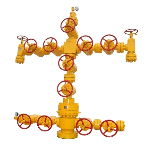
The standard cruciform layout dictates how technicians prioritize maintenance. This cross-shaped design allows fluid to flow straight up and turn 90 degrees into the production line. When inspecting an api 6a christmas tree, technicians focus on specific wear zones. The layout places different stress loads on different valves. Understanding these patterns prevents unexpected equipment failure.
Lower Master Valves: Usually operated manually. They sit at the very bottom of the assembly. They face full wellbore pressure continuously.
Upper Master Valves: Usually operated hydraulically. They sit just above the lower master. They act as the primary shut-in mechanism during routine operations.
Production Wing Valves: Located on the right side. They control fluid entering the flowline.
Kill Wing Valves: Located on the left side. They allow for chemical or fluid injection.
Choke Valves: Located downstream of the wing valve. They actively restrict and regulate flow rates.
Master valves require specific operational discipline. You must keep both lower and upper master valves fully open during normal operations. Partially closing them creates a throttling effect. Throttling causes high-velocity fluids to wash over the sealing surfaces. This erosion permanently damages the seals. Once damaged, the master valve can no longer hold pressure during an emergency. Always use the choke valve for flow regulation, never the master valve.
Wing valves act as crucial fail-safe mechanisms. Production wing valves are designed to be fail-safe closed. If hydraulic pressure drops, strong internal springs force the valve shut instantly. You must test these hydraulic pressure drops regularly. Testing ensures the springs have not weakened. It also confirms the internal gates slide freely without binding.
Kill wing valves serve a very different purpose. Operators often call the kill side the NASA (Non-Active Side Arm) in offshore environments. You use these injection ports to introduce methanol or specific corrosion inhibitors. Methanol prevents hydrate formation in cold subsea flowlines. Hydrates act like ice plugs. They can block production entirely. You must maintain these injection ports meticulously. Blocked kill valves prevent emergency well control operations.
The choke valve represents the highest-wear component in the entire assembly. Continuous fluid throttling happens here. Particulate abrasion from sand heavily damages the internal choke trim. As the trim wears down, it loses its ability to hold back-pressure. You must inspect choke trims frequently. Hardened materials like tungsten carbide help extend their lifespan. However, routine replacement remains a necessary operational reality.
Field-Tested Implementation and Repair Realities
Executing surface repairs requires careful risk mitigation. Many operators rely on traditional abrasive blasting to remove rust and old paint. You must expose the risks of this practice. Using abrasive grit near high-precision valves invites disaster. Tiny silica or slag particles easily penetrate protective seals. Once inside, they seize internal valve actuators. A seized master valve compromises the safety of the entire well pad.
We recommend safer alternative methods for surface preparation. Targeted bristle blasting provides excellent results without the loose grit. Localized wire-brushing also works well for small corrosion spots. These methods prevent abrasive debris from contaminating sensitive areas. They are especially useful during offshore or remote field refurbishments. You can execute these cleanings without shutting down production or building complex containment habitats.
Establishing standardized operating procedures (SOPs) extends component life dramatically. You do not always need to perform full-tree disassembly. Consistent, simple actions yield massive benefits.
Scheduled Valve Greasing: Inject correct API-certified lubricants to protect gate seals and displace trapped water.
Salt-Deposit Removal: Wash exterior surfaces on offshore platforms regularly to halt aggressive chloride corrosion.
Debris Clearing: Flush the body cavities of valves to remove settled sand before attempting to cycle them closed.
Visual Inspections: Check ring gasket connections for micro-leaks using ultrasonic acoustic detectors.
Best Practice: Always stroke your valves fully open and fully closed during lubrication. Cycling the valve spreads the grease evenly across the entire gate mechanism. It prevents the gate from sticking in one position over months of stationary production.
Evaluating Vendor Support, Scalability, and Compliance
Sourcing replacement parts demands strict adherence to industry standards. API 6A compliance is completely non-negotiable. Regulatory bodies require rigorous audit trails for all pressure-containing equipment. If a valve fails and causes an environmental spill, investigators will check your compliance records. Sourcing uncertified parts exposes your company to massive legal and financial liabilities. You must demand material traceability reports for every component.
You must also consider the scalability of your maintenance operations. Conventional surface trees offer relatively low maintenance scaling costs. Technicians can drive up to the well pad and swap a choke in hours. Subsea configurations present a totally different financial reality. Sending a remotely operated vehicle (ROV) to adjust a subsea tree costs thousands of dollars per day. Horizontal trees allow for easier well interventions, but they still require specialized pulling tools. Factor these access costs into your initial equipment selection.
Provide your decision-makers with strict shortlisting logic when evaluating equipment providers. Do not simply choose the lowest bidder. Look for strategic partnerships.
Verify the availability of OEM (Original Equipment Manufacturer) replacement parts in your specific geographic region.
Demand fully documented pressure-testing certifications for all assembled valves before they leave the factory.
Assess their retrofit capabilities. Can they easily install smart sensors on older equipment?
Check their field service response times for emergency breakdown situations.
Vendors who supply comprehensive training for your operators add immense value. A knowledgeable crew prevents accidental damage during routine operations. They know how to spot a failing seal before it bursts. Partnering with certified manufacturers guarantees your equipment meets exact metallurgical specifications. This attention to detail secures your asset's longevity.
Conclusion
The surface control assembly is never a "set-and-forget" asset. It stands as a dynamic control hub requiring strategic oversight and continuous care. Moving away from reactive repairs saves millions in preventable downtime. Precision maintenance extends the profitable life of your operations significantly.
Procurement and engineering teams should immediately audit their current surface equipment maintenance schedules. Verify your API compliance logs today. Consult with certified manufacturers to upgrade your highest-wear components. Consider integrating predictive sensors to catch pressure anomalies early. Taking these proactive steps ensures your wells run safely and efficiently for decades.
FAQ
Q: What is the difference between a wellhead and a wellhead Christmas tree?
A: The wellhead is installed during the drilling phase. It supports the heavy casing strings and seals the annular space in the wellbore. The tree sits directly on top of the wellhead. Operators install it for the production phase to control flow rates, manage surface pressure, and inject chemicals.
Q: How often should an API 6A Christmas tree be pressure tested?
A: Industry standards generally dictate routine hydrostatic testing and valve cycling every six to twelve months, depending on operational environments. High-corrosion or high-pressure wells require more frequent testing. This routine maintenance ensures all fail-safe mechanisms remain reliable under emergency conditions.
Q: Can you perform maintenance on a Christmas tree without shutting in the well?
A: Yes, certain tasks are possible. The swab valve and upper master valve allow limited wireline interventions. You can introduce tools into the wellbore while maintaining full pressure control. However, replacing major components like master valves requires shutting in the well completely.
Q: What causes wing valves to fail prematurely?
A: Premature failure typically stems from severe erosive wear caused by sand production. Corrosive fluids like hydrogen sulfide also degrade internal seals. Furthermore, improper surface cleaning techniques, such as using abrasive blasting near actuators, can introduce grit that mechanically binds the valve.


