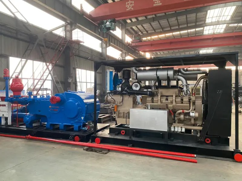
In high-pressure, high-temperature (HPHT) and complex directional drilling, fluid circulation failure directly translates to severe non-productive time (NPT). It also compromises well integrity. Equipment reliability under these harsh downhole conditions remains an absolute necessity. A sudden loss of hydrostatic pressure can trigger disastrous well control situations instantly.
Procurement and engineering teams must evaluate pumping systems beyond their upfront price tags. You need to meticulously assess long-term wear resistance, telemetry stability, and operational predictability. Frequent component breakdowns or unstable fluid pulse signals can easily derail an entire multimillion-dollar drilling program. Therefore, understanding the structural merits of your chosen equipment is critical for sustained operational success.
This guide breaks down the engineering realities of F-Series Drilling Mud Pumps. We provide a rigorous framework for evaluating technical specifications and matching pump capacity to rig horsepower. You will learn how to optimize component lifespans and ensure consistent, high-pressure fluid delivery across the most demanding well environments.
Key Takeaways
System Synergy: F-Series drilling mud pumps go beyond simple circulation; their pulse stability is critical for MWD/LWD (Measurement/Logging While Drilling) telemetry and blow-out prevention.
The TCO Baseline: Adhering to the "80% SPM (Strokes Per Minute) Rule" drastically reduces fluid-end consumable wear and extends equipment lifespans.
Rig Matching: Standardized deployment models exist for pairing pump models (e.g., F-1300 to F-2200) with specific rig horsepower ratings (1000 HP to 3000+ HP).
Compliance is Mandatory: Legitimate equipment must present transparent API 7K certifications, comprehensive NDT (Non-Destructive Testing) reports, and documented hydrostatic pressure tests.
The Strategic Role of Drilling Mud Pumps in Modern Well Operations
Industry professionals often frame the pump as the biological heartbeat of the drilling rig. These massive industrial units handle much more than basic fluid transfer. They circulate engineered drilling fluids down the drill string to cool the rapidly spinning bit. They aggressively clear rock cuttings from the wellbore. Most importantly, they maintain crucial hydrostatic pressure against the formation. This pressure prevents wellbore collapse and keeps volatile formation gases safely contained.
Modern downhole technology relies heavily on fluid dynamics. The output stability of your pump directly affects MWD/LWD data transmission. Measurement While Drilling tools use mud-pulse telemetry to send geological data back to the surface. Downhole tools create pressure waves in the fluid column. If a pump produces excessive mechanical pulsation, it masks these delicate telemetry signals. F-Series models maintain an exceptionally smooth discharge flow. This clarity allows drillers to interpret steering data accurately and make real-time directional adjustments.
Pump longevity ties directly to the efficiency of upstream solids control systems. Mud tanks, shale shakers, and agitators must work in perfect harmony. Poor solids control introduces abrasive sand and rock particles into the fluid. These abrasives act like liquid sandpaper. They prematurely destroy internal pump components like liners, pistons, and valves. Ensuring clean fluid intake is the absolute first step in maximizing equipment lifespan.
![F-Series Triplex Drilling Mud Pump Structural Diagram]()
F-Series Triplex vs. Alternative Configurations: A Structural Evaluation
Evaluating pump geometry reveals clear evolutionary trends in oilfield equipment. The industry has largely shifted away from older duplex (double-cylinder) models. Duplex pumps utilize a double-acting design. They move fluid on both the forward and backward strokes. This older geometry generates high discharge pulsation. Excessive pulsation subjects downstream manifold equipment to severe metal fatigue. Triplex models solve this issue entirely. They provide a significantly smoother fluid discharge rate. This smooth flow protects costly high-pressure piping from destructive vibration.
You might wonder why operators do not universally adopt quintuplex (five-cylinder) pumps. Quintuplex pumps do offer even lower pulsation metrics. However, F-Series Triplex models strike a vastly superior balance for most terrestrial and offshore rigs. Triplex designs feature fewer moving parts. They present a much lower maintenance complexity for rig mechanics. Fewer cylinders mean fewer valves, pistons, and liners to replace. This simplicity drastically lowers your long-term operating costs and reduces inventory burdens.
The widespread global adoption of the F-Series provides a massive standardization advantage. Drilling contractors value predictable maintenance protocols. When you deploy standardized F-Series Drilling Mud Pumps, you guarantee the global availability of interchangeable spare parts. A rig working in West Texas can source the exact same fluid end consumables as a rig operating in the Middle East. This cross-compatibility eliminates supply chain bottlenecks during critical well phases.
Structural Comparison of Mud Pump Geometries | Pump Configuration | Pulsation Level | Maintenance Complexity | Primary Industry Application |
| Duplex (2-Cylinder) | High | Moderate | Legacy rigs, low-pressure shallow wells |
| Triplex (3-Cylinder) | Low | Low | Standard HPHT drilling, directional wells |
| Quintuplex (5-Cylinder) | Very Low | High | Specialized offshore setups, continuous fracing |
Core Engineering Dimensions: Evaluating the Power and Fluid Ends
Understanding a mud pump requires dissecting its two primary halves: the power end and the fluid end. Each section demands specific metallurgical and engineering standards to survive continuous heavy-duty operation.
Power End (Stability and Drive)
The power end converts rotational energy from the rig motors into linear reciprocating motion. This section must absorb massive mechanical stresses without deforming.
Structural Integrity: Quality manufacturers utilize fabricated steel plate frames. These heavy-welded frames eliminate dangerous harmonic resonance during high-load operations. Cast iron frames often crack under extreme stress. Steel plate construction ensures absolute rigidity.
Transmission: Internal gear design dictates energy transfer efficiency. Herringbone gears remain the industry standard. Their opposing angled teeth engage smoothly. This geometry transfers extreme torque while entirely eliminating axial thrust. It protects the main bearings from lateral destruction.
Lubrication: Continuous operation generates immense internal heat. Dual-system lubrication is strictly necessary here. A splash lubrication system bathes the main gears in oil. Simultaneously, a forced-feed system injects oil directly into the crosshead guides. This dual approach prevents catastrophic metal-on-metal friction.
Fluid End (High-Pressure Containment)
The fluid end manages the actual intake and highly pressurized discharge of the abrasive drilling mud. It acts as the primary wear zone.
Material Science: You must demand forged alloy steel components. Industry-leading modules utilize 35CrMo steel. Manufacturers treat this alloy to achieve a specific core hardness. This specific hardness withstands intense internal abrasion and chemical corrosion from synthetic polymer muds.
Valve and Piston Design: The internal geometry must support standardized API valve formats. Standardized sizes ensure seamless rapid replacements on the rig floor. The robust fluid end design must confidently handle continuous high-pressure ratings. Top-tier modules easily sustain operational pressures up to 7,500 PSI without structural fatigue.
Rig-to-Pump Matching Framework: Sizing for Operational Efficiency
Pairing the correct pump size to your specific rig horsepower is a foundational engineering task. Oversized pumps waste capital and deck space. Undersized pumps fail prematurely due to constant maximum-load operation. The industry relies on a proven capacity matrix to standardize these equipment pairings.
Rig Horsepower to Pump Capacity Matrix | Rig Horsepower Rating | Recommended Pump Model | Standard Quantity per Rig | Typical Well Depth Profile |
| 3000 HP Land Rigs | F-2200 | 3 to 4 Units | Ultra-deep exploration, extended reach |
| 2000 HP Rigs | F-1600 | 3 Units | Deep conventional, complex directional |
| 1500 HP Rigs | F-1600 | 2 Units | Standard horizontal pads, mid-depth |
| 1000 HP Rigs | F-1300 | 2 Units | Shallow to medium depth conventional |
Deep-well operations utilizing 3000 HP rigs require immense fluid volume. They typically deploy three to four F-2200 units. This configuration provides necessary redundancy and high-volume flow for extended-reach laterals. Standard 2000 HP setups rely on three F-1600 units. Meanwhile, lighter 1000 HP rigs effectively standardize on dual F-1300 configurations.
Engineers consistently advise operators to follow the "80% Operation Rule." You should size your pumping system so target flow rates (GPM) and pressures (PSI) are achieved at 80% of the pump’s maximum rated Strokes Per Minute (SPM). Operating continuously at 100% SPM generates excessive heat and destroys valves rapidly. This 20% operational buffer drastically reduces consumable wear rates. It extends the life of liners and pistons exponentially. Running larger pumps at slower speeds always proves more efficient than running smaller pumps at their absolute mechanical limits.
Adapting to Harsh Environments: Custom Configurations and Upgrades
Drilling environments rarely offer ideal conditions. Standard factory models require specific environmental upgrades to survive extreme climates and highly abrasive geologies. Procurement teams must specify these upgrades during the initial purchasing phase.
Offshore and high-corrosion settings present severe challenges. Saltwater spray degrades standard carbon steel within weeks. Rigs operating in marine environments require comprehensive material upgrades. You must specify stainless steel hardware for all exposed fluid end fasteners. The outer chassis demands multi-layer, zinc-rich anti-corrosion marine coatings. Furthermore, offshore platforms often prefer hydraulic drive options over traditional mechanical chain drives. Hydraulic drives offer precise variable speed control. They integrate seamlessly into automated offshore power grids.
Arctic drilling operations face the opposite extreme. Extreme cold weather alters the viscosity of lubricating oils. Attempting to start a frozen power end will immediately shatter internal gears. Arctic kits are mandatory for these regions. You must install heavy-duty immersion heaters directly inside the power end oil basin. These heaters maintain optimal oil viscosity during winter shutdowns. They ensure safe, frictionless cold-starts when operations resume.
Operations targeting high-abrasive formations require internal hardening. Pumping high-density, high-solid drilling fluids accelerates fluid end erosion. Operators facing these geologies specify specialized hardened cylinder liners. These bi-metal liners feature a high-chrome inner sleeve. Additionally, standard rubber valves fail quickly under these conditions. You must upgrade to heavy-duty polyurethane valve inserts. Polyurethane resists chunking and tearing when processing sharp sand and dense barite mixtures.
Quality Assurance & Compliance: Vetting Manufacturer Claims
The global oilfield market contains varying levels of manufacturing quality. Operators cannot rely on marketing brochures alone. You must vet manufacturer claims through rigorous, standardized compliance documentation. Inadequate metallurgy in a fluid end module can cause catastrophic explosive failure under 7,500 PSI loads.
You must insist on verifiable API 7K and API 11E certifications. Legitimate manufacturers proudly display verifiable API monograms. These certifications ensure the equipment meets rigorous international petroleum industry design and safety tolerances. Do not accept "API compatible" as a substitute for official certification. The manufacturing facility must pass external metallurgical audits.
Before accepting delivery, engineering teams must demand three specific testing protocols:
Hydrostatic Testing: Factories must test forged fluid cylinders to at least 1.5 times their maximum rated working pressure. For example, a module rated for 7,500 PSI must successfully hold 11,250 PSI during factory testing without sweating or deforming.
Non-Destructive Testing (NDT): Surface inspections are insufficient. Require comprehensive Ultrasonic Testing (UT) and Magnetic Particle Testing (MT) reports. These tests scan all load-bearing cast and forged components for microscopic internal voids or hairline cracks.
Full-Load Bench Testing: Demand Factory Acceptance Test (FAT) documentation. The manufacturer must run the fully assembled unit on a test stand. They must prove operational performance, temperature stability, and vibration limits under simulated field loads prior to shipping.
Conclusion
Choosing the right drilling mud pump requires a strategic approach. You must align your rig horsepower, anticipated well depths, and environmental realities with a standardized F-Series model. Properly matched equipment creates a reliable foundation for aggressive drilling programs. It prevents sudden pressure losses and keeps complex downhole tools communicating clearly.
Your primary focus must always remain on operational uptime. The upfront capital expenditure of heavy machinery is secondary to the long-term reliability of the fluid and power ends. Deploying equipment with globally standardized API parts ensures your rig mechanics can source replacements instantly. This standardization prevents minor valve failures from causing major operational delays.
To move forward successfully, buyers should audit manufacturer testing facilities directly. Review all material certification reports for fluid end forgings carefully. Furthermore, calculate your required flow rates and pressure demands strictly based on the 80% SPM rule. This proactive approach guarantees your pumping system will deliver maximum longevity and consistent hydraulic power.
FAQ
Q: What is the ideal SPM to run an F-Series mud pump for maximum lifespan?
A: Engineers strongly recommend operating at or below 80% of the pump's maximum rated Strokes Per Minute (SPM). This 80% rule provides an operational buffer. It drastically reduces heat generation and minimizes wear on fluid-end consumables while still meeting target flow requirements.
Q: Can F-Series fluid end parts be interchanged between different manufacturers?
A: Yes. Components that strictly conform to standard API 7K dimensions are generally 100% interchangeable across major industry brands. This universal compatibility significantly reduces supply chain risks and inventory costs for drilling contractors.
Q: What is the difference between single-acting and double-acting mud pumps?
A: Modern F-Series models are single-acting triplex pumps. They draw and discharge fluid only once per stroke. This design lowers pulsation and dramatically simplifies maintenance compared to older double-acting duplex designs, which move fluid on both forward and backward strokes.
Q: How often should the power end oil be changed?
A: Standard industry practice dictates an initial oil change at 200 operating hours. This clears out microscopic break-in debris from the gears. Following this, operators should change the oil every 2,000 hours or semi-annually, depending on climate severity and workload.


